There are design considerations when considering electronics
- What is the application?
- Which readout device is being used and why?
- Positive or Negative HV?
- Count rate: Typical and Maximum
- What are the electronics that the detector will be connected to?
- Preamp question: Charge sensitive or I to V converter
- Charge Sensitive preamps are typically used with shaping amplifiers
- I to V converter preamps are typically used with digitizers
Standard Plug-on electronics
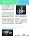
Voltage dividers and voltage divider/preamplifiers allow for the supply of proper voltage distribution to the light-sensing device, such as a photomultiplier tube, and for the transmission of the signal to your system electronics.
Voltage dividers used by us are resistive (or transistorized) devices specially designed to accelerate electrons from the cathode to the anode of a phototube.
Any of these devices can be hard-wired to the light-sensing device in an integrated package.
- Voltage Divider for PMTs
- Voltage Divider/Preamplifier Combinations
- Integrated High Voltage Power Supply
A standard voltage divider distribution is usually specified by the PMT manufacturer for each photomultiplier tube.
Standard Designs optimized to work with our standard detectors
- P-1210: 12-pin voltage divider for 10-stage PMT
- P-1410: 14-pin voltage divider for 10-stage PMT (8-stage option available P-1408)
- T-1410: 14-pin fully transistorized voltage divider for 10-stage PMT
- Negative high voltage option available
- Model P-1210N
- Model P-1410N
Note: AS20, AS2612, AS2712 were designed specifically for use with LaBr detectors to optimize the performance benefits
However, such a standard configuration is not always the optimum one for a specific application.
The voltage divider can be custom designed to take into account the photomultiplier characteristics and the performance if specific gain, linearity or timing is a requirement.
A dynode output can be added on specific request. A dynode tap output is used to provide a linear signal when a phototube is operated at such a high gain that anode output is non-linear. This is often the case with fast-timing phototubes.
The charge delivered at the output of the photomultiplier must be converted to a voltage pulse. This is done by a preamplifier.
In addition, a preamplifier maximizes the signal/noise, operates as a cable driver to send the signal to the main amplifier, which can be a distance from the detector.
Provides an output pulse to be fed to the spectroscopic amplifier consistent with the NIM standard. Typically, the decay time is 50μs.
Standard Designs optimized to work with Saint-Gobain Crystals standard detectors
- PA-1210: 12-pin voltage divider with preamplifier for 10-stage PMT
- PA-1410: 14-pin voltage divider with preamplifier for 10-stage PMT
(8-stage option available Model PA-1408) - TA-1410: 14-pin fully transistorized voltage divider with Preamp for 10-stage PMT
- Negative high voltage option available
- PA-1210N
- PA-1410N
- TA-1410N
The high voltage power supply contains a voltage divider, charge-sensitive preamplifier and power supply assembled in one package. It has excellent stability with varying anode currents, very low power consumption,
low noise and optimized to work with our Scintillation detectors.
Standard Designs
- HVPA-1210: 12-pin voltage divider, charge-sensitive preamplifier and power supply in one package for 10-stage PMT
- HVTA-1410: 14-pin voltage divider, charge-sensitive preamplifier and power supply in one package for 10-stage PMT

We can provide radiation detection expertise and multi-channel analyzer (MCA) up to pulse shape analysis. All you will need to do is plug in the USB cable and you are ready to collect data.
Solution for all detection needs (gamma, neutron, alpha, beta, X-ray) with standard or customizable detectors.
- Matching solution to the application
- Ready to use detection platform for developers
- One-stop shopping – fully optimized vertical integration
- Reduced development time, cost and risk
- Ideal solution for high count rate applications
The basic configuration is a Detector / MCA but you can choose to add on the Computer Interface Module and Wireless connectivity.
- Quick access to the market
- Reduced development time and cost
- Single source for full detection solution
- Reduced acquisition cost
- Reliable – perfect matching between components
- Open-source, open-access application for programmers
- Low power USB based MCA
- Low power embedded computer
- Extended battery life for mobile systems
- Over 30-hour operation on a single battery
- Add additional counting detector without additional electronics
- Open Source Linux OS and API
- Option
- Performance stabilization for NaI(Tl) and LaBr3 detectors
- Providing a constant gain over the operating temperature range
- Providing a constant energy resolution over the operating temperature range.
- Maintaining the best possible pileup rejection
- Stability of ±5% between -20°C and +50°C
- Performance stabilization for NaI(Tl) and LaBr3 detectors
MCA usbBase – typical features
- USB-powered & controlled
- On-Board energy histogram 4096 x 32
- Accurate count rates and real-time measurement
- List mode: stores energies and timestamps
- Low-power HV unit
- Open-source application programmer's interface (API in Python and C++)
- GPIO supports DAQ synchronization between modules.
- Morpho Data Server supports native apps and web-browsers
MDS (Morpho Data Server)
- The Morpho Data Server (MDS) handles the low-level USB communication with the eMorpho MCA units.
- Clients connect to the MDS via native apps or a web browser.
- Clients can be local or remote.
- Clients can run on any platform, under any OS and can be written in most languages
Our stabilized detector solution addresses all three challenges by:
- Providing a constant gain over the operating temperature range
- Providing a constant energy resolution over the operating temperature range
- Maintaining the best possible pileup rejection
It is known that NaI(Tl) based scintillation detectors exhibit gain change over their operating temperature range. Typically, when coupled to a bialkali photomultiplier tube and operating with an integration time of 1µsec, the NaI(Tl) detectors will exhibit an overall gain change between -20°C to +50°C of ≈30%. This change in gain reduces the low-energy sensitivity of the detector while operating at high temperatures, and clips the maximum measurable energy when the detector is cold.
In addition, NaI(Tl) scintillators exhibit several decay time constant components. The primary single exponential decay constant is 250nsec at room temperature. As the temperature decreases, the longer time constant components increase in intensity. When operating a system with a fixed integration time, an artificial degradation in pulse height resolution (PHR) will be observed. At room temperature, 1µsec integration time is sufficient to collect approximately 90% of NaI(Tl) scintillation pulse. At 0°C this time increases to ≈2µsec and at -40°C it is ≈6µsec. Without collecting 90% of the scintillation pulse light, the energy resolution will degrade and overall system performance will suffer. Finally, any attempt at pile-up rejection does depend on the pulse shape. The pulse shapes change with temperature (getting slower below room temperature, and faster above). The parameters governing the pile-up rejection must change accordingly, to maintain strong pile-up rejection over the temperature range.
The detector firmware automatically adjusts the relevant parameters, such as integration time and pileup rejection as a function of temperature. A built-in temperature-compensated LED provides a reference light pulse that is used to ensure gain stability over time and temperature. Once a detector has been calibrated and gain stabilization enabled, the autopilot routine within the detector firmware takes over and maintains the gain while adjusting the parameters in order to ensure optimum detector performance (stability of ±5% between -20°C and +50°C). The routine preserves the energy window of interest while ensuring a near-constant pulse height resolution.
| Scintillator | Model | Crystal size | PMT dia. | PHR @Cs-137 | Part# | Note |
|---|---|---|---|---|---|---|
| NaI(Tl) | 2M2/2-MCA-X | 2" dia. x 2" thick | 2" | ≤ 6.6% |
|
MCA Base |
| NaI(Tl) | 2M2/2-LED-MCA-X | 2" dia. x 2" thick | 2" | ≤ 6.6% |
|
MCA + Gain Stabilized |
| LaBr3 | 38SEA38 /2-MCA | 1.5" dia. x 1.5" thick | 2" | ≤ 3.0% |
|
MCA Base |
| LaBr3 | 38SEA38 /2-MCA | 1.5" dia. x 1.5" | 2" | ≤ 3.0% |
|
MCA Base |
| LaBr3 | 51SEA51 /3-MCA | 2" dia. x 2" thick | 3" | ≤ 3.0% |
|
MCA Base |
| LaBr3 | 51SEA51 /3-MCA | 2" dia. x 2" thick | 3" | ≤ 3.0% |
|
MCA + Gain Stabilized |